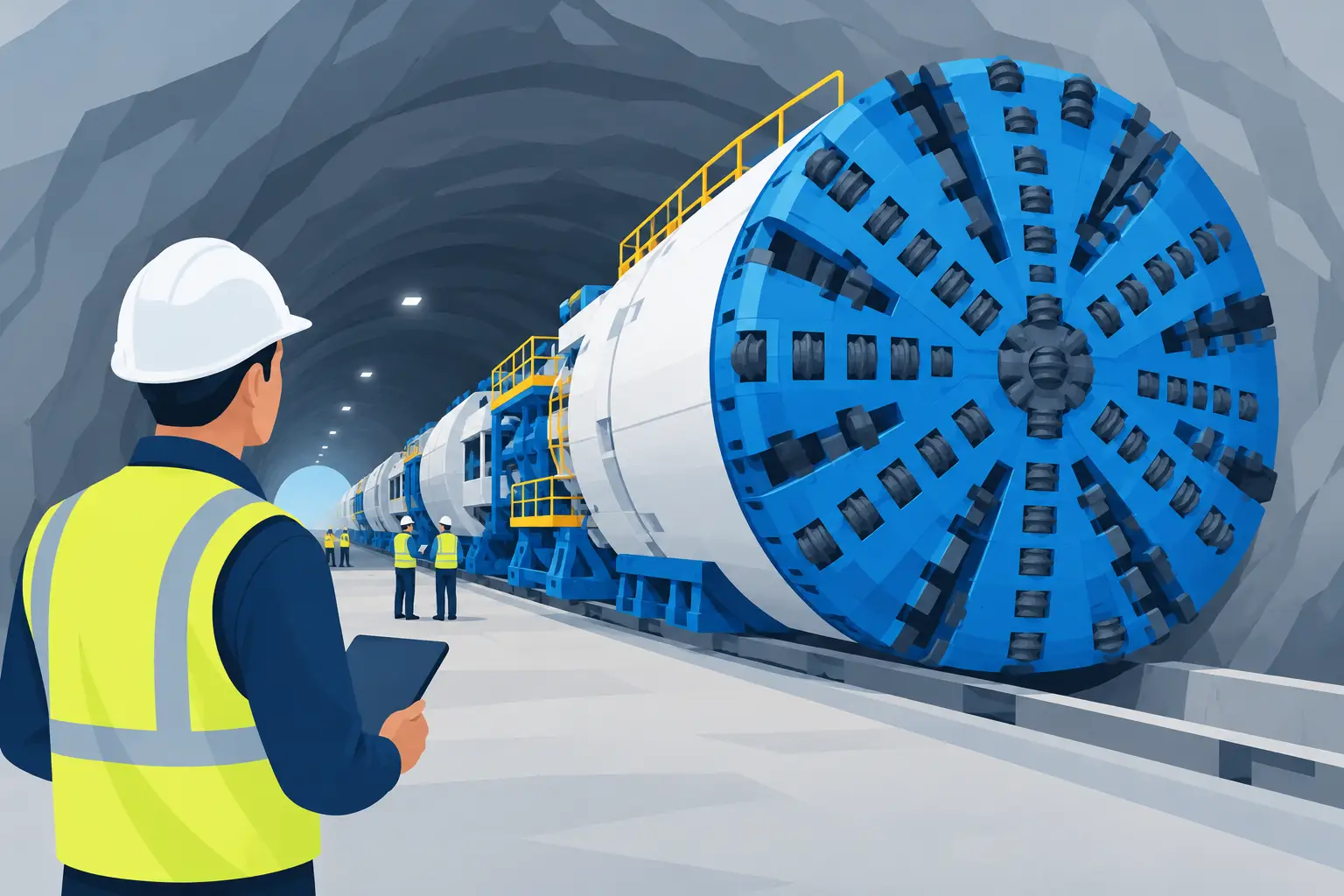
A conveyor interlock that appears to work during a quiet inspection can still fail when the system is under load, operating remotely, or passing material through a transfer point. In tunnelling, civil works, mining and other high-demand operations, that gap can expose people to unexpected movement and turn a minor fault into extended downtime. Knowing how to test conveyor interlocks properly means confirming the safety function, the control logic and the practical response of the entire conveyor sequence.
Interlock testing is not a box-ticking exercise. It must be planned and completed by competent, authorised personnel under the site isolation, permit and commissioning requirements. The exact method depends on the conveyor design, PLC logic, access arrangements and the work being performed. A test that is appropriate for a short surface conveyor may not be suitable for a long underground system with multiple drives, remote start stations and linked plant.
What conveyor interlocks are designed to do
An interlock prevents, permits or stops conveyor operation when a defined condition exists. It may stop a downstream belt from starting before an upstream belt is ready, prevent restart after a pull-wire trip, or inhibit operation when a chute blockage, belt drift, low speed or guard switch fault is detected.
The distinction between an operational interlock and a safety function matters. Some interlocks protect process flow and equipment, such as a downstream permissive or level switch. Others are directly connected to personnel safety, including emergency pull-wires, guard-door switches and emergency-stop circuits. Both need testing, but safety-related functions require stricter control, documented proof testing and clear authority to return the system to service.
Before testing begins, confirm the approved drawings, cause-and-effect documentation, electrical schematics, PLC input and output list, and current site procedures. If these documents do not match the installed system, treat that mismatch as a defect. Do not assume that a field modification, temporary jumper or altered sequence is understood by every operator.
Prepare the system before testing
A disciplined setup avoids the most common interlock-testing failure: testing one device while another person assumes the conveyor is available to run. Start with a pre-start discussion involving the electrical, mechanical and operational personnel affected by the test. Define the scope, the test boundary, communications method and who has control of the system.
Review the risk assessment and decide which parts of the test can be completed de-energised, which require control power, and which require controlled functional operation. Isolation and lock-out/tag-out arrangements must reflect all energy sources, including electrical supply, stored mechanical energy, hydraulic equipment and connected conveyors that may feed into the same transfer area.
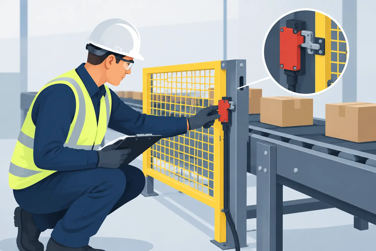
Inspect the physical devices before operating them. A correctly programmed input cannot compensate for a seized pull-wire switch, damaged cable, misaligned belt-drift roller, blocked proximity sensor or guard that no longer engages its switch. Check labels and identification against the drawings so that the device being tested is the device shown in the control system.
Where production conditions prevent a full test, record the limitation and agree on an alternative controlled test window. Leaving a device unverified because access was inconvenient is not an acceptable close-out for a critical conveyor system.
How to test conveyor interlocks before production
Testing should follow the system sequence rather than treating every field device as an isolated point. For a multi-conveyor arrangement, begin at the discharge end and work back through the feed conveyors. This confirms that downstream equipment is proven available before upstream equipment is permitted to run and reduces the risk of material being delivered to a stopped belt.
Prove the normal start and stop sequence
With the system in its approved test condition, issue a normal start command and observe the sequence. Confirm the correct conveyor starts, any start warning operates as designed, and upstream equipment is held until the required downstream permissive is present. Verify normal stop behaviour as well. Depending on the design, belts may stop in a controlled order to clear material from transfer points.
Do not rely only on HMI indications. Observe local status lights, contactor operation, drive status and belt movement where it is safe to do so. A screen can show a healthy signal while a failed relay, wiring fault or drive configuration prevents the field equipment from responding correctly.
Test each field interlock at the device and in the control system
Operate each interlock by its intended means. For example, activate a pull-wire switch, open an interlocked guard where authorised, operate a belt-drift switch, simulate a low-speed condition using the approved test method, or trigger a chute blockage device. Confirm three outcomes: the correct input changes state, the required conveyor response occurs, and the fault is clearly shown to the operator.
For a safety-related device, verify whether it causes an immediate stop, inhibits a start, or both. Then confirm reset behaviour. The conveyor must not restart merely because the device has returned to its normal position. It should require the fault to be cleared and the designated reset and start procedure to be completed. Automatic restart after a safety trip is a serious control issue unless specifically engineered and permitted under the applicable safety requirements.
Where a device protects a particular conveyor section, confirm the trip affects the intended equipment and any linked equipment required by the cause-and-effect schedule. A pull-wire on one belt may need to stop several belts feeding a common transfer. Conversely, a trip should not unnecessarily stop independent plant if that creates another operational or safety risk. This is why the approved logic, not assumptions, must govern the test.
Verify remote, local and maintenance modes
Conveyors often have more than one control location: a local station, a control room HMI, a PLC panel or a remote production control system. Test that interlocks remain effective from every permitted control mode. Changing from local to remote must not defeat a safety input or leave an old start command active.
Maintenance and bypass modes require particular attention. Any bypass must be authorised, time-limited where the system design allows, visible to operators and removed before handover. A bypass should never become an undocumented workaround for a nuisance trip. Repeated trips point to an underlying mechanical, electrical or process issue that needs repair.
Assess faults rather than resetting them away
An interlock that trips intermittently is not necessarily a faulty interlock. It may be identifying belt misalignment, material build-up, low belt speed, a failing drive, damaged cable, water ingress or poor adjustment. Resetting the fault without identifying the cause can place the system back into service with the same exposure still present.
When a test fails, place the equipment in a safe state, preserve relevant fault history and investigate methodically. Check the device condition, wiring terminations, power supply, PLC input status, logic configuration, output response and mechanical condition. If the fault involves a safety circuit, use the project escalation process and do not return the conveyor to normal operation until the required repair and verification are complete.
Record results for safe handover
A useful test record identifies the conveyor and device, the test method, expected response, actual response, date, personnel involved and any defects or limitations. It should also record the status of temporary links or bypasses and confirm their removal. This provides the maintenance team with a baseline and gives project management evidence that commissioning or post-repair checks were completed under control.
For conveyor systems supporting continuous tunnelling, records should also capture operational effects. A trip at a transfer point can affect TBM spoil removal, stockpile capacity, downstream plant availability and shift planning. Clear information allows supervisors to decide whether the issue can be repaired during a planned window or needs an immediate response.
Give complex systems the time they require
Long conveyors, multiple drive arrangements and confined underground installations need more than a quick trip test. Communication delays, limited visibility, restricted access and connected plant all change the risk profile. Test plans should nominate observers at critical locations, establish positive radio communication and set clear stop-work authority before any functional run.
After installation, upgrade or repair work, an independent check by competent electrical and mechanical personnel can identify issues that are easily missed when one team has been focused on completing the job. This is particularly valuable after control-panel changes, belt extensions, drive replacements or modifications to transfer arrangements.
A well-tested interlock system gives operators confidence that a conveyor will respond predictably when conditions change. When the result is uncertain, keep the system out of service, document the fault and bring in qualified support. HP Rural applies that same controlled approach across conveyor commissioning, maintenance and breakdown work where safety and uptime must operate together.